MEMBER
of the
POD |

|
|
All Grain Brewing
After a year of making beer
from malt extracts, I decided to try my hand at brewing from whole
grains. Using whole grains has its advantages, it is cheaper,
you have more control over the final product and the beer tastes
better. Of course taste is opinion but I look at it this
way, it is like food from a can vs. food made from scratch, the
from scratch usually taste better. The drawbacks are it
is a lot more work and more to learn. A brew day used to
be a couple hours now it is all day. But, its a labor of
love.
While thinking about getting
into whole grain brewing, I decided to do infusion mashing.
That involves adding water heated to a specific temperature to
the grains in order to arrive at a temperature that the grains
would rest at for a specific length of time to allow enzymes to
convert the starches to sugar. Sounds complicated but it
really isn't. There are charts, formulas and programs out
there that tell you what temperature you have a volume of water
to reach your rest temperature.
I didn't intend to build
a RIMS when I decided to get into whole grain brewing. It
just kind of evolved out of control. I bought 2 ten gallon
Gott coolers, a Phil's Phalse bottom and a Phil's sparge arm.
At the same time, I bought a boil kettle set up and an outdoor
burner from Sabco. A pump wasn't even in my plans at this
point, I wanted to use gravity as much as possible. As I
sat down and started planing out how I was going to make this
all work together smoothly, I quickly realized that I would have
to have a set up that was way too tall. I decided to get
a pump to make the transfer from the boil kettle to the carboys
and hot liquor tank easier. At least this way, I could leave
the boil kettle on ground level.
The frame was built, the
pump installed, everything was ready to go. Then I made
the mistake of surfing the web and looking at other people's RIMS.
I was hooked. I based the heating element control part of
my RIMS on the setup built by Keith Royster, who has been very helpful in
answering my questions and working with me on design problems.
Thanks Keith. The rest of the design is from my own imagination.
I am not going to repeat all of the information that Keith put
on his page, he did an excellent job. I just want to show
the way I did it.
|
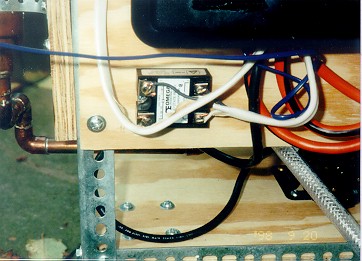
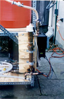
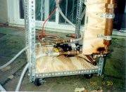
One place I diverged a little from Keith's design
is the heating element housing. Instead of taking the element
out from the top for cleaning and having to leave the wires exposed
to the environment and my accidental touch, I used a compression
fitting in the center of the element housing that allows me to
open the housing so I can clean the element after the mash.
After talking to Keith about temperature overshoot, he suggested
moving the thermocouple to the output side of the heating element
vs. the input side as is shown in his original design.
I tried that but it didn't work out well for me so I moved it
back to the input side. In this picture, you can also see
the PID (temperature controller) that is mounted in the
side of a plastic breaker switch box. |
|
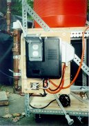
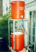
This is a front view of the breaker switch box
that houses all of the electronic components. The power
is run from an outlet on the house into a GFI outlet on the right
side of the breaker box. The pump and the PID are plugged
into the GFI outlet. I put switches in the circuit so I
can turn the pump and the PID on and off as needed without unplugging
them. Below the box, you can see the Solid State Relay(SSR)
that the PID uses to turn the heating element on and off. |
|

|
This is a close up view of the SSR. The
right side comes from the output on the PID, polarity matters
at this point so it is important the the wire in the positive
output is the same wire on the positive input. The left
side of the SSR controls the heating element. The polarity
doesn't matter on this side so you wire it just like a light
switch, one of the wires is split and connected to both sides.
The PID doesn't supply power to the heating element, it just
controls the switch. The heating element gets its power
from the same circuit as the PID. |
|
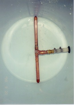
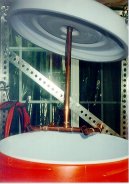
My return manifold is a simple H shape.
Nothing spectacular here, I just tried to center the output in
the four quadrants of the mash tun. I had to drill a hole
in the top of the lid so I could adjust the height of the manifold
depending on how much grain is in the mash tun. This is
the only permanent modification that I had to make to the Gott
coolers. |
|
|
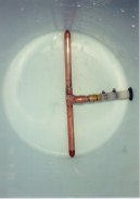
I started out using a Phil's Phalse bottom but
couldn't get it to work. I was afraid that the thick pad
included with the Phalse Bottom would restrict the liquid flow
and I couldn't get it to stop floating without the pad.
The black rubber gasket fits the 1/2" braided hose very
snug. I bought the gasket at the hardware store and then
used a little dish soap to lubricate it enough to feed the hose
into the bucket. The manifold has small holes drilled in
the bottom to allow liquid to flow but keep grain from getting
in. It fits snug to the sides of the cooler and stays in
place quite nicely. |
|
The pump is the heart of the system. I
got mine from Moving
Brews, they were very knowledgeable and helpful, I highly
recommend them. The far side of the picture is where the
input from the mash tun and boil kettle comes in. The near
side is where output is directed to the heating element and to
a hose that I can use to fill the hot liquor tank, carboys and
the boil kettle during sparging. |
|
|
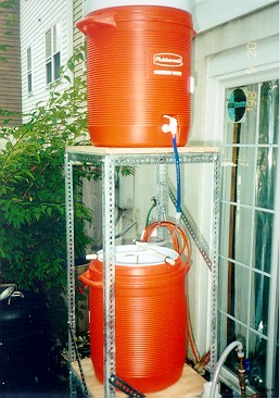
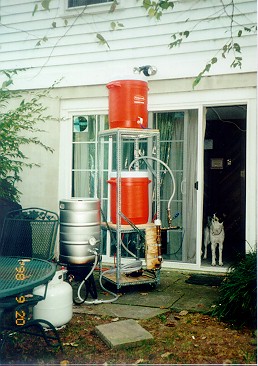
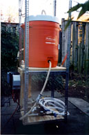
Here, I have the system set up for sparging.
I found it easier and faster to fill the hot liquor tank on the
ground and lift it to the top shelf of the rack. The pump
will fill the cooler without having to take it down but it takes
quite a while. Gravity drives the flow of water to the
Phil's Sparge Arm and causes the arm to spin and evenly distribute
water over the grain bed. There is an in-line valve below
the blue hose that I can use to adjust the rate of flow into
the mash. I use one of the ball valves to control the flow
into the boil kettle. |
|
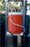
Recent additions to the system are two quick
disconnects that let me take the mash tun completely off the
stand so I can easily dump out the spent grains and clean the
cooler without soaking my electronic components. |
|